3.19.2. Roadbed
To create a roadbed:
-
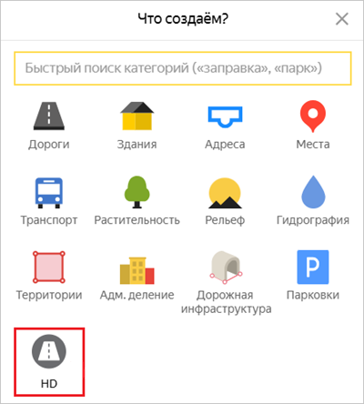
Click Create. In the panel that opens, select HD:
-
Select Roadbed from the list:

Roadbeds are polygonal items: when editing them, follow the rules for drawing polygonal items in Yandex Map Editor (see 2.7. Polygonal items).
Use arcs to smoothly draw rounded elements of the roadway and areal markings:
-
Select a point at the beginning of the roadbed curve.
-
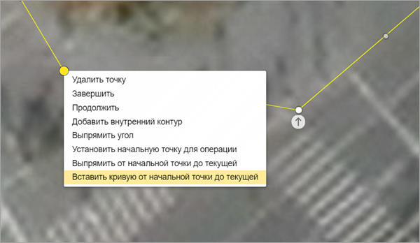
Right‑click the point to open the context menu, then select Set the operation starting point.
-
At the point where the roadbed curve ends, open the context menu and select Insert a curve from the starting point to the current point.
-
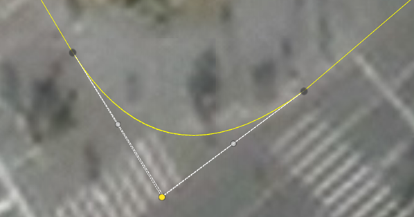
You'll see an arc connecting the start and end points — you can edit it by moving the auxiliary nodes.
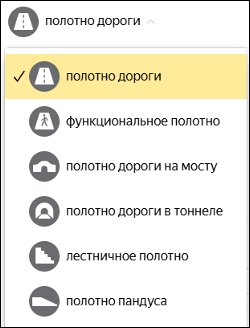
The following roadbed types are available:
-
Structural types that indicate the road's location: on a bridge, in a tunnel, on the ground, or over another structural roadbed.
-
Functional types that indicate the road's purpose: pedestrian road, motorway, and so on.
3.19.2.1. Structural types
There are five primary structural roadbed types, plus one additional type used for drawing items over a primary structural roadbed. The primary types are:
-
Roadbed — for roads that don't run over bridges or in tunnels.
-
Roadbed on bridge — for roads that run over bridges.
-
Roadbed in tunnel — for roads that run in tunnels.
-
Flight of stairs — for pedestrian staircases leading onto road bridges or into tunnels.
-
Ramp surface — for ramps.
Use the additional type, functional roadbed, to draw items whose functional type differs from that of the main roadbed.
You may overlap roadbeds of the primary structural types, but you can't draw them end‑to‑end.
Note
Flights of stairs are an exception: draw them end-to-end, without overlapping other primary or additional structural roadbed types.
3.19.2.2. Functional types
The following functional roadbed types are available:
-
Roadbed — for motorways.
-
Tram tracks — for tram tracks.
-
Railway tracks — for railway tracks that run as a distinct roadbed on a separate surface.
-
Under construction — for long‑term motorway repairs.
-
Pedestrian road — for pedestrian roads.
-
Physical island, separator — for physical traffic islands, barriers, and similar items.
-
Railway crossing — for railway tracks crossing motorways, pedestrian roads, or tram tracks.
-
Vegetation/flowerbed — currently unused.
-
Service area — for:
-
Class 7 roadbeds leading to parking areas.
-
Class 8 roadbeds located on large paved areas (parking lots near malls, major transport facilities, stadiums), as well as access roads to these parking areas.
The service area type serves a similar functional purpose to the roadbed type, so the same rules apply when drawing it.

-
If a road includes items of multiple functional types, the roadbed of a primary structural type should have the functional type that occupies the largest area.
There are two ways to draw a road within specified boundaries:
-
With overlap: Draw a roadbed of a primary structural type along the specified road boundaries, assigning it the same functional type as the road. Then, draw roadbeds of the Functional roadbed structural type with additional functional types over it. This is the preferred drawing method.
-
End-to-end: Draw a roadbed item along the motorway boundaries. Then, draw roadbeds of other types end‑to‑end with it, each within its own boundaries, as separate structural roadbeds with their own functional types (for example, a pedestrian road).
You may use and combine both drawing methods. For example, you can draw a pedestrian road as a structural type end‑to‑end with a motorway, then draw tram tracks over it as a functional type.
Alert
Draw functional roadbeds with the physical island, separator functional purpose only using the overlap method. In other words, always place a physical traffic island or separator over another structural roadbed.
Example
The screenshot shows a road bridge with tram tracks running along its center, separated by a curb:
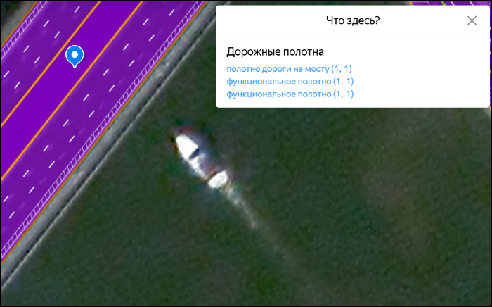
The item was drawn as a structural roadbed of the roadbed on bridge type. Two structural roadbeds of the functional roadbed type were then added over it — one of the physical island and one of the tram tracks functional type.
3.19.2.3. General principles for drawing and attributing roadbeds
3.19.2.3.1. General principles for drawing roadbeds
-
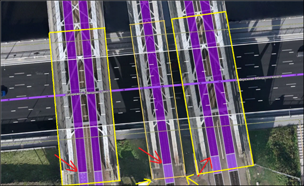
The boundaries of tram and railway roadbeds (including tram and railway bridges, as well as their descents and ascents) must align with the boundaries of the bridges and embankments on which the tracks run.
Example
The screenshot shows the correct markings in yellow. The purple polygonal items and red arrows indicate incorrect markings for the bridge with railway tracks.
Draw the roadbed along the boundaries of the bridge itself (along the railings or another structure along the bridge's edge), not along the boundaries of the sleepers.
-
For motorways and adjacent pedestrian sidewalks, the roadbed includes the roadway and its shoulders — either up to the curb, or, if there is no curb, up to the edge of the pavement:

Additionally, a roadbed may include parts of pedestrian roads, tram tracks, and railway tracks that are directly adjacent to the road, provided they are drawn as separate roadbeds of their corresponding functional types.
Note
To make it easier to draw along the boundaries of polygonal and linear markings, we recommend selecting Roadbed: polygons in the roadbed settings. This makes the layer transparent, so you can clearly see the markings underneath:

-
Draw motorway-only roadbeds on class 1–7 roads, excluding roads intended only for pedestrians or cyclists.
Draw roadbeds on class 8 roads only in the following cases:
-
At airports: for roads used for transit traffic, as well as for airport parking areas.
-
On large paved areas such as parking lots near major malls, transport facilities, and stadiums.
-
-
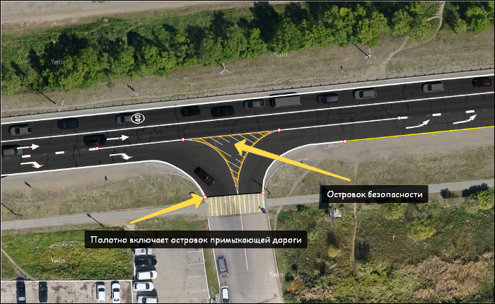
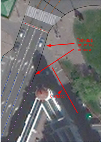
If you're drawing a roadbed that connects to an adjacent road with no roadbed:
- Via exit ramps and a traffic island: include the traffic island in the roadbed.
Example
- Without exit ramps or a traffic island: draw the roadbed as a smooth line, even if the physical merge between the adjacent road and the main is uneven (has edges of different length).
Example
-
If the priority road at a T-shaped intersection turns instead of continuing straight, don't round the junction.
Example
Correct
Incorrect
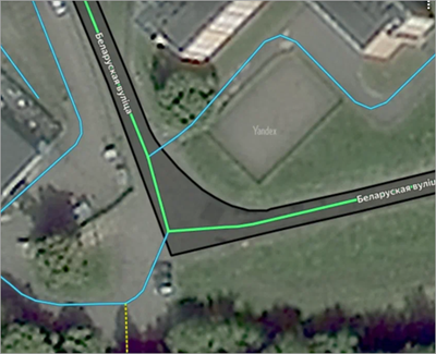
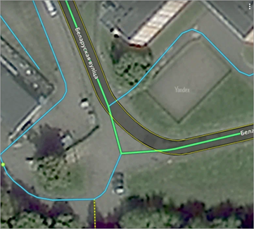
-
When drawing a roadbed, pay attention to the linear markings that define the roadway boundaries. The distance between these markings and the shoulder determines how to draw the roadbed:
-
If the distance is less than two meters, draw the roadbed along the marking line.
-
If the distance is more than two meters, draw the roadbed and the markings according to their actual positions.
-
-
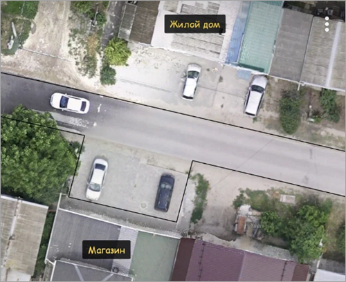
In residential areas, don't include parking spaces near residential buildings in the roadbed. However, the roadbed should include parking spaces near other types of buildings, such as industrial buildings and offices.
Example
-
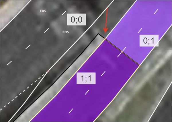
When you draw three or more roadbeds at different levels, they must not share any points at the same intersection. The example below demonstrates an incorrect approach.
Example
-
Include parking pockets in the roadbed even if they are physically marked with a different type of pavement or a low curb:

Additionally, the roadbed should include parking pockets that lack hard pavement but have a parking sign.
Example
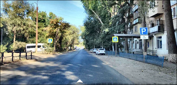
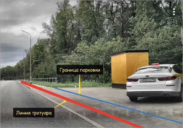
Warning
If a parking pocket is separated from the roadbed by a sidewalk or a bike path, don't include it in the roadbed. In this case, treat it as a separate parking area, not a parking pocket.
-
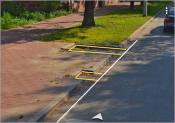
Don't include small recesses (like those intended for manhole covers) in the roadbed, regardless of markings. Don't confuse such recesses with parking areas or pockets:
-
When drawing a roadbed, you can split it — for example, if you reach the point limit or need to change the roadbed type or level.
Avoid creating overly complex items — split them into simpler ones.
-
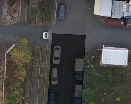
The end of a roadbed should be straight, without any rounding.
Example
-
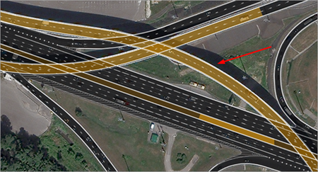
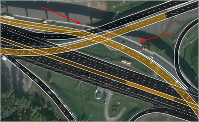
When drawing a roadbed, follow satellite images. Don't try to adjust for displacement caused by the shooting angle. The only exception is when the physical road section boundaries differ from the image due to ongoing construction or repairs.
Correct
Incorrect
3.19.2.3.2. General principles for attributing roadbeds
3.19.2.3.2.1. Roadbed levels
A roadbed can have the following levels:
-
[0;0]: Most roads, including descents into tunnels and ascents to bridges.
-
[0;-1], [-2;-1], and so on: Exit ramps leading into tunnels.
-
[0;1], [2;1], and so on: Exit ramps leading to bridges and overpasses.
-
[1;1], [2;2], [-1;-1], [-2;-2], and so on: Multi-level bridges and tunnels.
Warning
Roadbeds that share any numeric level value must not intersect, but they may have adjacent boundaries.
For example, a roadbed with levels [1;0] may intersect with any roadbed that doesn't have 0 or 1 in its levels:
-
May intersect: [-1; -1], [2; 2], and so on.
-
May have adjacent boundaries with: [0; 0], [-1; 0], [1; 1], [1; 2], and so on.
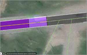
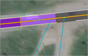
Make sure the transition level doesn't have any vertices connecting more than two motorway sections.
Examples
|
Correct |
Incorrect |
|
|
|
|
|
|
3.19.2.4. Drawing functional and structural roadbed types
3.19.2.4.1. Roadbed on bridge
Determine its boundaries the same way as for a regular roadbed.
Additionally, a roadbed on a bridge may include directly adjacent parts of pedestrian roads, tram tracks, and railway tracks, provided they are drawn as separate roadbeds of their corresponding types.
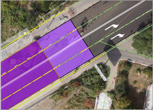
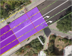
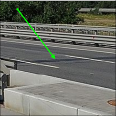
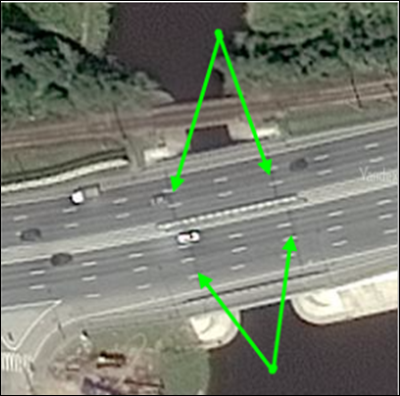
A roadbed on a bridge is a part of the roadbed — determine its boundaries using one of the following methods, in order of priority:
-
By expansion joints, if visible in the source materials (panoramas, dashcam images, satellite images):
-
By the points where the bridge meets the ground, if the expansion joints aren't visible:
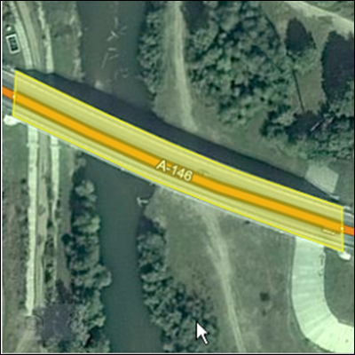
Only align the roadbed, road graph, and road structure if these items were drawn and attributed according to the rules (see 3.3.2.6. Type of structure) and appear in the HD maps with minimal or no deviation from the real world.
Example
The blue arrows show the expansion joints in the 2023 image. However, the road graph was correctly drawn and attributed based on the 2022 image. Given the short distance between the joint and the node, you may connect the bridge roadbed to the road graph intersection:
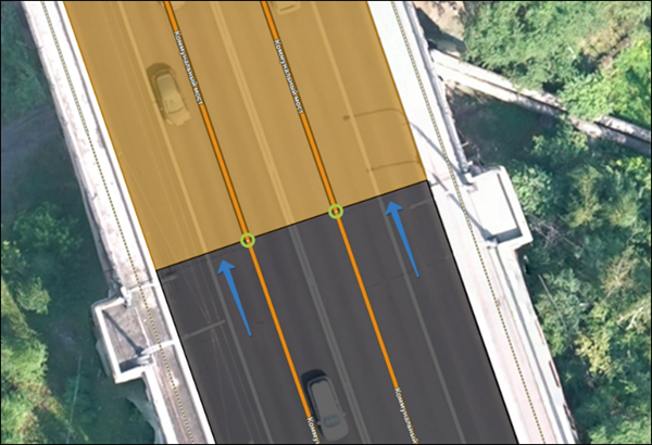
A roadbed on a bridge may have levels [1;1], [2;2], and so on.
If there are any road markings on the bridge, link the bridge roadbed to them. Use the existing road graph as a reference and create these items where they appear in the graph.
The road sections that approach a bridge and have the values [0;1] or [1;0] for levels A and B shouldn't be longer than the bridge itself.
Approach road sections are not part of a roadbed on a bridge.
Transition levels ([0;1], [2;1], and so on) for approach road sections are assigned arbitrarily on the roadbed section with the appropriate set of levels.
Roadbeds with matching levels (1-0, 1-2, and so on) must not intersect if their actual elevation directions are opposite.
When setting the level A and level B attributes, follow the general mapping rules in section 3.3.2.5. Level (A) and Level (B).
3.19.2.4.2. Roadbed in tunnel
A roadbed in a tunnel is a part of a tunnel extending from one portal to the other.
Determine its boundaries the same way as for a regular roadbed.
Additionally, a roadbed in a tunnel may include directly adjacent parts of pedestrian roads, tram tracks, and railway tracks, provided they are drawn as separate roadbeds of their corresponding types.
A roadbed in a tunnel must have levels [-1;-1], [-2;-2], and so on.
If there any road markings in the tunnel, link the tunnel roadbed to them. Draw a tunnel up to the point where it connects to the roadbed.
The road sections that approach a tunnel and have the values [0;-1] or [-1;0] for levels A and B shouldn't be longer than the tunnel itself.
Approach road sections are not part of a roadbed in a tunnel.
When setting the level A and level B attributes, follow the general mapping rules in section 3.3.2.5. Level (A) and Level (B).
3.19.2.4.3. Physical island
A physical island is a small section of fencing or an artificial elevation above the pavement.
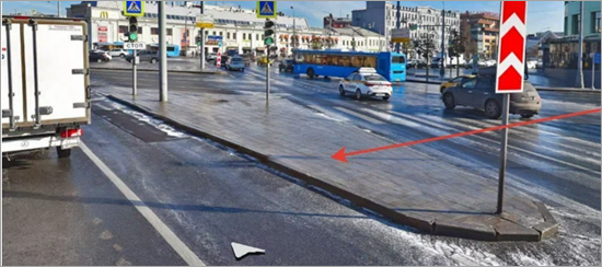
Draw a physical island in the following cases:
-
A physically separated space between the edges of roads with the two-way road attribute, provided it has no major pedestrian infrastructure like squares or parks.
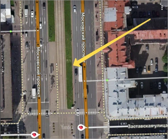
-
A physically separated space within a roundabout, provided it has no major pedestrian infrastructure like squares or parks.
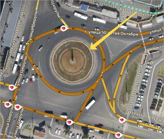
-
A physically separated space between exit ramps at an at-grade junction, including when that junction is part of a grade-separated junction and the space between the exit ramp and the main roadway lies within the boundaries of a single intersection.
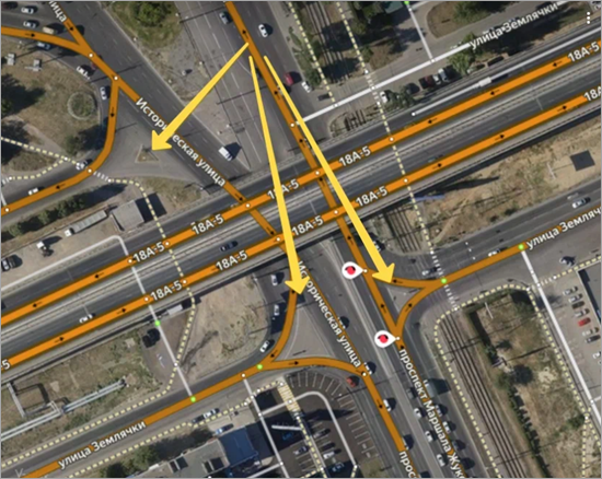
-
A physically separated space between the lines of a two‑line road, occupied by elevated or lowered tram tracks directly adjacent to the roadway.
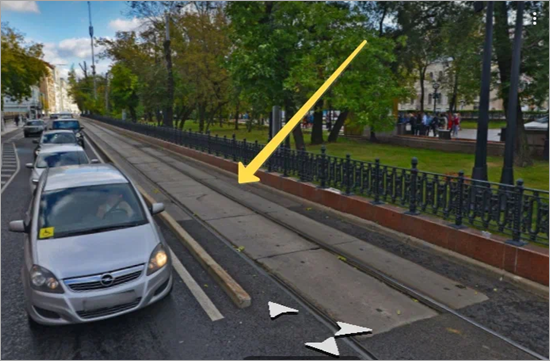
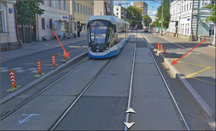
-
Small sections of fencing or other artificial elevation located on the roadbed but not touching its edge.
For example: bridge pillars separating traffic lanes, barriers at toll booths, or small grass areas within parking pockets.
-
On class 8 roads, also draw physical islands on small physical separators located within a wide, continuous roadbed (for example, small physical separators between adjacent driveways in a parking area). Examples of such traffic islands:
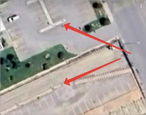
Don't draw a physical island in the following cases:
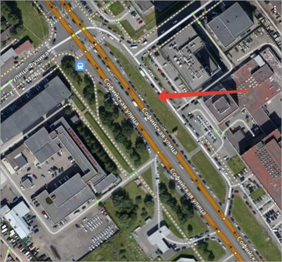
-
A physically separated space between the main road and a road with a "U‑turn", "frontage road", or "none" design feature.
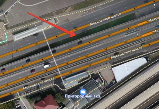
-
A physically separated space between two-line roads if that space lies under a bridge at the point where the bridge meets the ground.
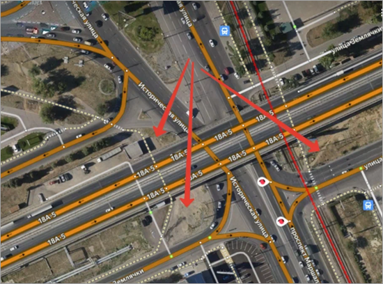
-
A physically separated space between exit ramps at a grade-separated junction where the ramps connect roads intersecting at different levels within the junction.
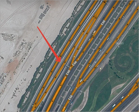
-
A physically separated space between two-line roads if that space lies under a bridge at the point where the bridge meets the ground, or above a tunnel at the point where the tunnel goes underground.
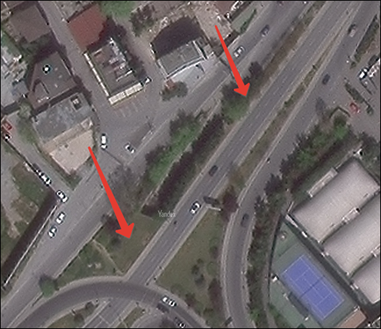
Below are the rules for attributing and drawing physical island boundaries:
-
Draw a physical island over the roadbed and don't cut it out of the roadbed.
-
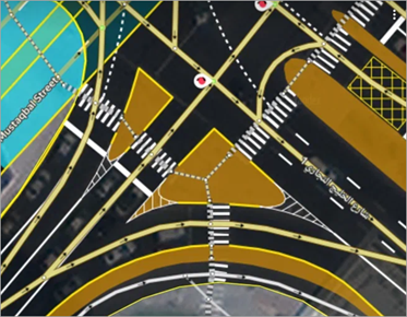
If there are linear markings indicating the edge of the roadway along the physical island, draw the physical island polygon based on the distance between the roadway edge marking and the item separated by the physical island:
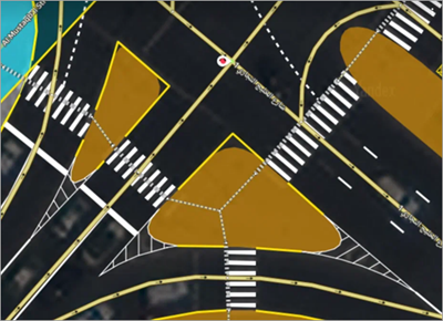
- If the island isn't enclosed by exit ramps and the distance is less than two meters, extend the physical island polygon to the roadway edge marking — in this case, determine the polygon length by its physical boundary.
Example
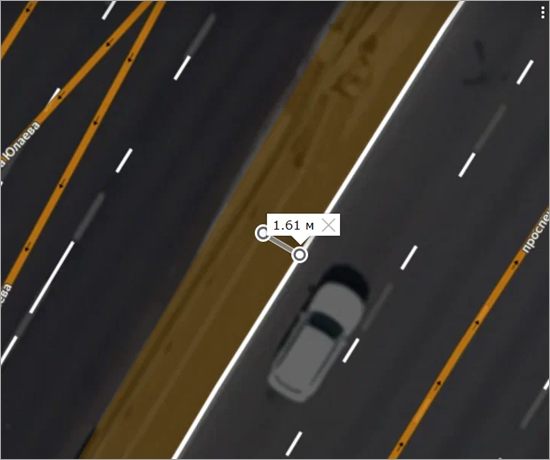
- If the distance exceeds two meters or the island is enclosed by exit ramps, draw the physical island polygon and the roadway edge marking using their actual locations.
Example
Correct
Incorrect
-
When drawing a physical island on a roadbed with levels other than zero, assign the island the same level as the roadbed it sits on.
-
If the physical island is partially level with the ground but has a continuous curb, draw it as a single physical island.
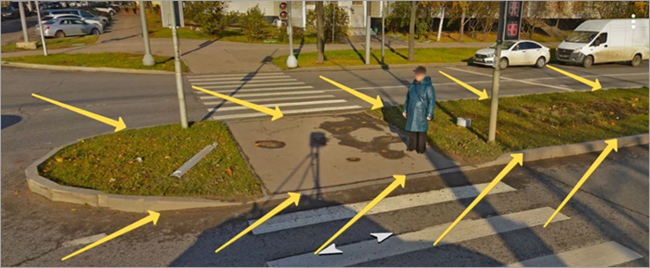
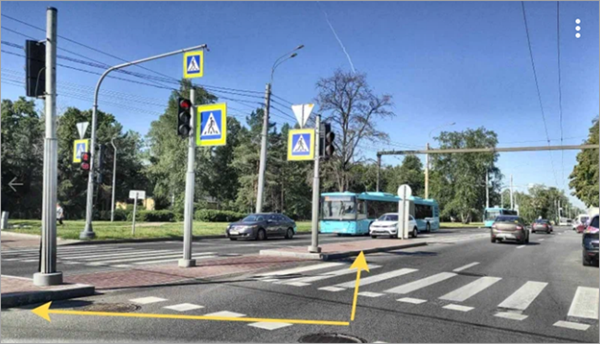
However, if a gap or depression doesn't share a continuous curb with the physical island, draw it as multiple separate islands.
-
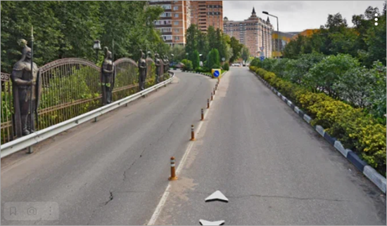
Draw bridge pillars, road posts (non‑continuous barriers), median strips, and dividers at toll booths as a single physical divider, without creating separate items:
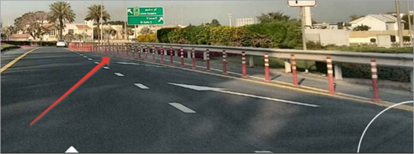
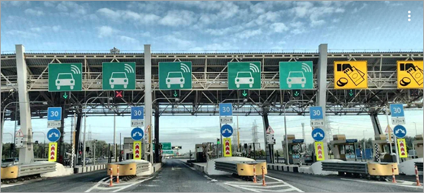
Note
if road posts are aligned exactly with the linear markings, draw both items (physical island and linear markings).
Example
-
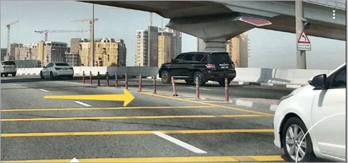
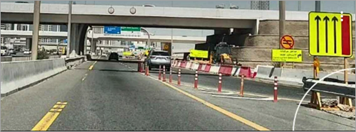
Physical and legal islands may overlap if the physical island is represented by road posts that can't be cut out of the polygonal marking due to their size.
Examples
3.19.2.4.4. Tram tracks and railway crossings drawn over the roadbed
Note
Railway crossings are equivalent to railway tracks. The following rules apply to both railway crossings and railway tracks.
Draw tram tracks and railway crossings as a polygonal item:
-
On top of a previously drawn roadbed (without cutting into it) if they are at the same level as the roadbed.
-
On a physical divider if, for example, the tracks are higher or lower than the roadbed (even if they are physically separated from the roadway).
Draw tracks that are level with the roadway in the same way as a physical divider, using the road markings as a guide.
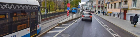
When tracks are higher or lower than the roadbed, mark the transition with a physical divider.
Note
-
Include the track slabs in the track polygon.
Examples
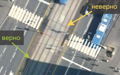
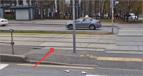
-
Determine the track boundaries by the boundaries of slabs, sleepers, and other infrastructure.
-
If the distance from the track boundary to the edge of the physical island is less than two meters, draw the tracks along the island edge.
-
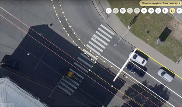
Draw straight track sections as a continuous roadbed, but split it at junctions to match the actual track layout.
Example
-
Draw roadbeds for individual tram and railway bridges from the beginning of the bridge embankment or pillar.
Example
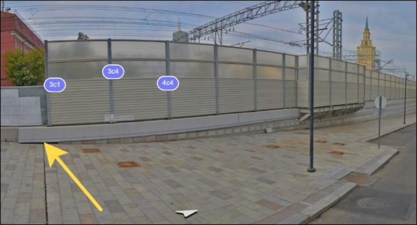
3.19.2.4.5. Vegetation, flowerbed
Until further notice, don't draw vegetation, lawns, or flowerbeds on HD maps.
Don't delete existing vegetation/flowerbed items from the map.
3.19.2.4.6. Under construction
Draw an "under construction" roadbed only if the construction or repairs within the same roadbed boundaries will continue for more than three months. If the construction period doesn't exceed three months, don't draw the "under construction" polygon.
For long‑term construction, draw the under construction polygon over the roadbed polygon:
-
Required: when repairs don't cover the full roadbed width.
-
Preferred: when repairs cover the full roadbed width.
Note
If a road is fully closed for construction or repair but a detour is available, draw a roadbed on the detour route and an "under construction" polygon on the main route.
This polygon shouldn't contain any markings. Don't draw physical islands.
3.19.2.4.7. Pedestrian road
Draw a pedestrian road from the roadway curb (inclusive) to the outer boundary of the sidewalk, such as a building or a fence.
Pedestrian roads shouldn't include driveways to courtyards or adjacent areas that cross the sidewalk. In addition, they shouldn't include the outer boundaries of fences, parapets, or similar structures.
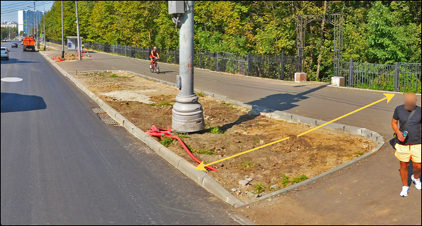
Note
Pedestrian roads should include:
-
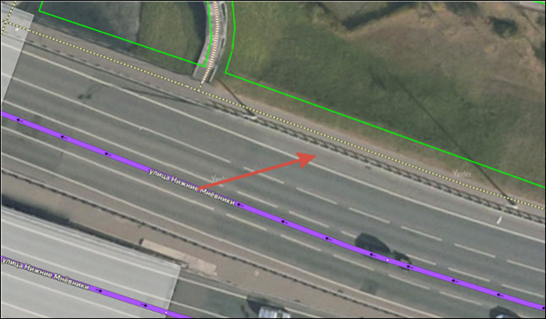
On bridges and near bridges: spaces between the edge of the roadway and the curb that delimits the roadway.
Example
The satellite image shows the distance between the edge of the roadway and the curb:
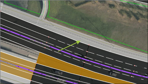
Draw a pedestrian roadbed along the edge of the roadway, ensuring that no gaps remain between the roadway and the pedestrian roadbed.
-
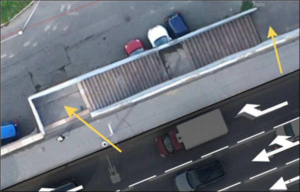
Stair landings adjacent to the sidewalk on a bridge or in a tunnel.
Example
3.19.2.4.8. Flight of stairs
Use flights of stairs only for straight-flight pedestrian staircases leading onto road bridges or into tunnels. Don't draw flights of stairs to represent spiral staircases.
When drawing flights of stairs, follow these rules:
-
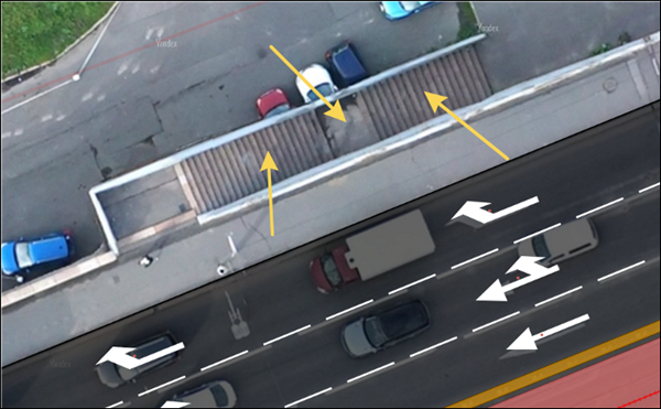
Include the sections representing intermediate landings in the roadbed.
Example
-
At ground level, start drawing a flight of stairs from the beginning of the first step.
-
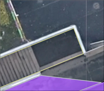
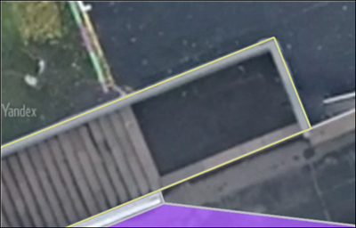
Don't include railings or parapets in the roadbed.
Example
Correct
Incorrect
-
Connect flights of stairs to roadbeds where Level A matches Level B.
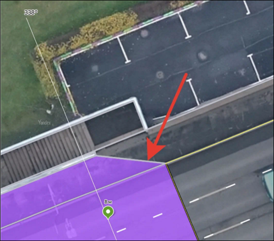
If a transition level (0‑1 or other) appears at the top (for bridges) or at the bottom (for tunnels), split the roadbed to connect at a non‑transition level. The goal is to keep the roadbed and road section levels consistent — the transition level must not have any road crossings.
Example
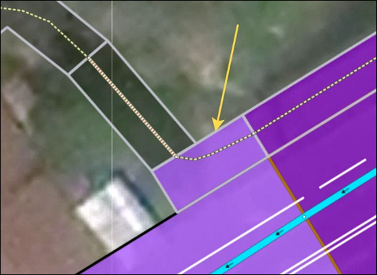
In some cases, you may connect to a level 0-1 roadbed if it won't create a road crossing at the transition level.
Example
-
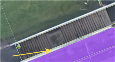
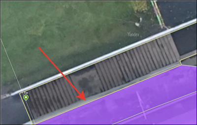
Leave a gap between a flight of stairs and the roadbed on an embankment or bridge, extending it to the point where they meet at the top landing.
Example
Correct
Incorrect
-
Draw a flight of stairs end-to-end, without overlapping other primary or additional structural roadbeds.
3.19.2.4.9. Ramp surface
Draw ramp surfaces only for pedestrian roads.
Ramp surface boundaries must follow pedestrian road boundaries, excluding side curbs, fences, and other barriers.
Example
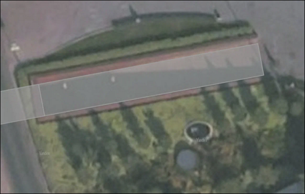
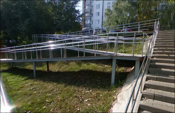
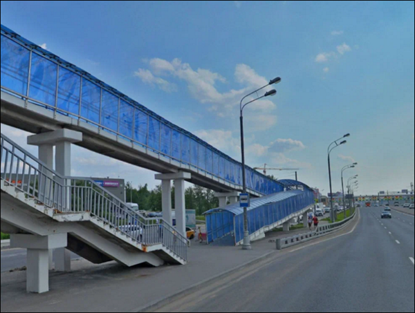
Draw a ramp if it meets at least one of these conditions:
-
The ramp runs along changing terrain or leads onto an overpass or bridge, provided the ramp is built on supports or other artificial structures.
Examples
-
The ramp leads to an underground pedestrian crossing.
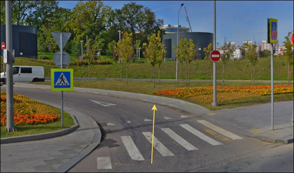
Don't draw a ramp in the following cases:
-
The ramp runs alongside a staircase or is mounted on one.
-
The ramp leads to building entrances.
-
The physical item isn't a ramp but rather a sloped pedestrian road that follows the terrain.
Example
Just like flights of stairs, ramp surfaces must connect to roadbeds where Level A matches Level B.
If a transition level (0‑1 or other) appears at the top (for bridges) or at the bottom (for tunnels), split the roadbed to connect at a non‑transition level. The goal is to keep the roadbed and road section levels consistent — the transition level must not have any road crossings.